CAD Modelling of Elegoo
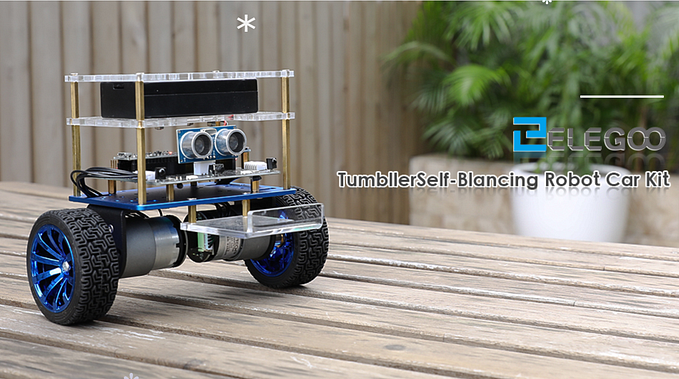
This blog will detail the intricacies of my CAD modelling of the Elegoo Robot. As stated in my general blog, I’ve decided to wait until the Elegoo arrives to construct it via SolidWorks. I understand a lot of my classmates have started and rendered their models, but I think I’d utilise my time best working on the Rube Goldberg Machine and the Ping Pong Launcher. I’ll update this blog as soon as it arrives!
2nd March

As previously posted on the general blog, here’s the list of components. I’ll be developing each part separately then assembling it using CAD software known as SolidWorks. Here’s a list of all the components:
Tyres x 2

Motor Bracket x 2

Motors x 2

Ultrasonic Sensor x 1

Aluminium Alloy Board x 1

Fastener for Battery Box x 1

Top Plate x 1

Battery box (Lithium Batteries) x 1

Elegoo Board x 1
6P Cables x 2
M3 K-type gear nut x 2

M3*12 Pan head machine screws x 2

M3*23 Double-pass copper cylinder x 4
M3*45 Single-Pass Copper Pillars x 4
M3*6 Pan head machine screws x 29

M3*5 Countersunk Screws x 11

M3*11 Double-Pass Copper Column x 7

M3*18 Double-pass copper column x 2

M4*6 Round head Phillips screws x 6

Coupling x 2

Bill Of Materials for the Elegoo
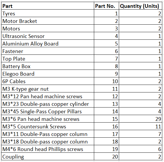
There’s not a huge amount of info to put into the BOM but I thought it was good practice. It’s a nice checklist of items, however I think there was a slight variation in the user manual I found online and the version we ordered. The battery box is a different shape, the fastener has different hole locations and the K-Type Gear nuts are not needed.
4th March
Still no Robot! I’m holding off as long as I can until I have to start. I’d love to have the robot in advance so I could get a real feel for the object and be able to design it more accurately. Don’t worry, I’m not procrastinating, in the meantime try check out my other blogs on the Ping Pong Launcher and Rube Goldberg machine.
9th March
Well… it seems very uncertain from today’s class that the Robots will ever arrive. I have no choice but to get properly started. I’ll be using a Computer Aided Design Software known as SolidWorks. I’ve used in a few times previously but never to the detail I’ll go into in this project.

Systematic Design Process
I plan to try be as systematic as possible when designing this, but the nature of design is that this won’t happen. I’ll be uploading all my parts into a highlight reel on Instagram if you want a better visual conception. Here are the steps I plan to stick to as I build this:
- Build Simple individual parts
- Build rough versions of more complex parts — Ultrasonic Sensor, Elegoo Board etc.
- Assemble parts
- Add colour
- Complete detail of more complex parts — Ultrasonic Sensor, Elegoo Board etc.
- Finalise mates
- Final Render
Simple Individual Parts.
Many of these parts have a relatively simple geometry. A classmate who managed to order a robot sent along a few measurements to help us get started and I eyeballed the rest.
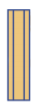
The Aluminium Plate, Top Plate and Fastener
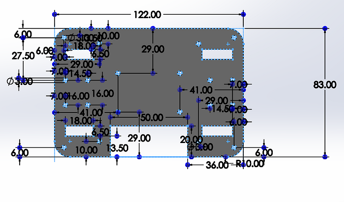
These pieces consisted of a simple extruded boss, fillets and many extruded cuts. The most difficult part was figuring out where the holes went as they had to align with the other pieces accurately. After spending hours using sketch picture, I managed to get rough dimensions. I also realised it doesn’t really matter as long as all the three pieces had holes in the same locations.
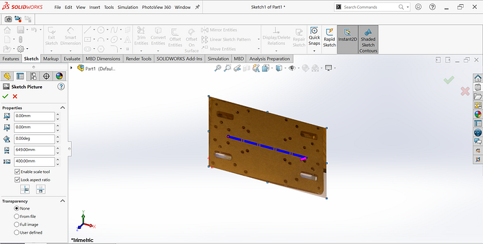
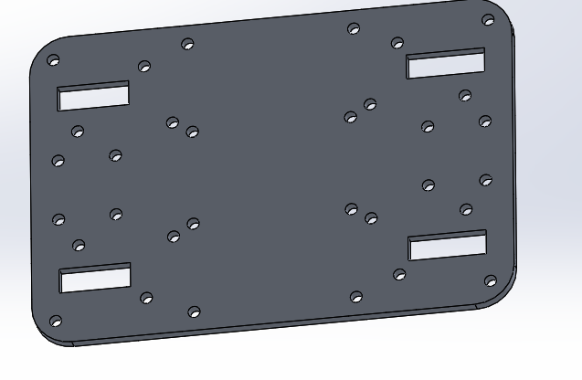
The Aluminium Plate and Top Plate are the same piece, just different materials, so that saved a lot of time. Then the fastener was the exact same except for a small extruded square at the bottom
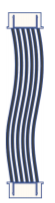
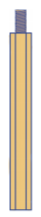
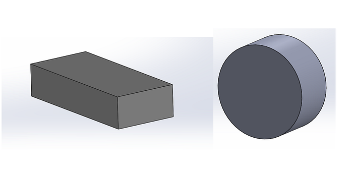
Copper Columns
12th March
The Copper columns were great. I just extruded a hexagon to a varying length depending on the specification of 11mm, 18mm 23mm or 45mm
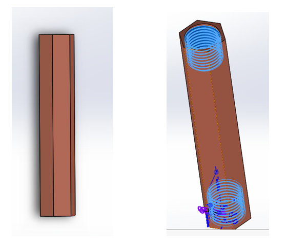
I then extruded a 3mm cut on both ends depending on whether it was single or double pass. Then I used hole wizard to thread it as seen above.
Wheels and Battery Holder
Keeping these simple for now just to get a good estimate of the dimensions. I’ve a good idea of what to do later.
Motor Bracket
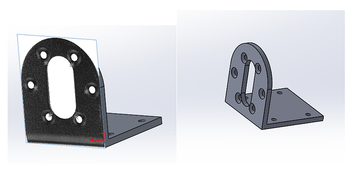
I took inspiration from the Plate sketch Picture trick. Consisted of extruded cuts, 3pt arcs and then hole wizard to countersink the holes. Countersunk holes are good because they make the screws sit a bit neater.
More Complex Components
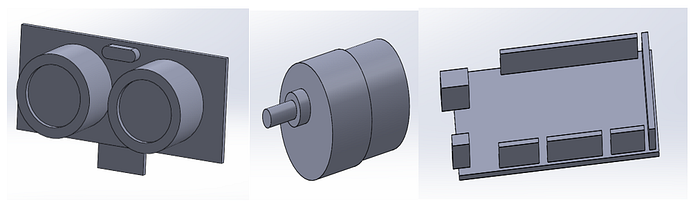
As previously stated, keeping simple for now. I made all these using pretty simple extrudes. I’ll go into more detail when I finalise them.
Well that’s the majority of components constructed, I’ll try see how I get on assembling them all tomorrow.
Introduction to the assembly
13th March
Similar to Lego, assembling in SolidWorks just consists of joining parts together via mates. The majority of the ones I used were coincident and concentric.
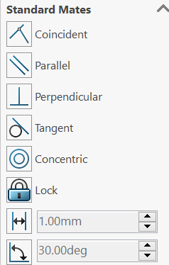
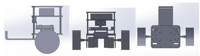
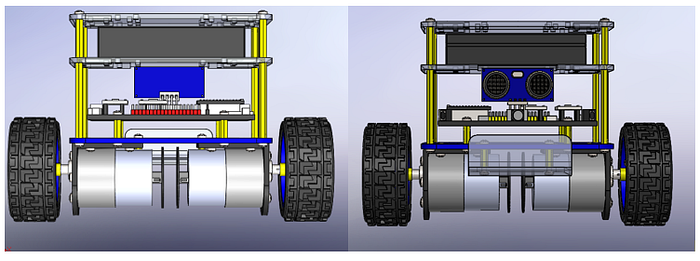
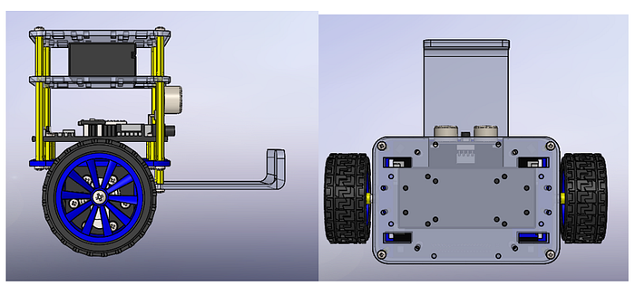
Using mates in SolidWorks can get a bit complicated, given the sheer number of mates used. After numerous errors, I managed to get a good draft assembly done. It took most of the day but it was extremely satisfying to see it come to life

It’s great to see it finally come together a bit. Here’s a few more views below:
The next steps I’ll take will be
- Add colour and specify materials in each part
- Add far more detail into components such as the ultrasonic sensor, motors, microcontroller and in particular the wheels.
- Check mates and other dimensions
- Render!
14th March
Detailed construction of individual components
So obviously the wheels aren’t looking great currently. To construct the wheels I thought it best to make two separate parts; the tyre and the frame.
The Frame:
The key to SolidWorks is breaking it down as much as you can into many small steps. A simple extrusion followed by a revolved cut and a loft to connect the two parts was all it took.
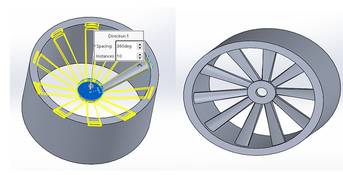
A pattern of the loft rotating around the wheel and a quick extruded cut and my frame is done. I set the material to be an aluminium alloy.
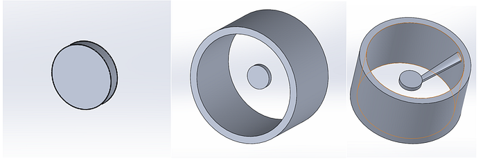
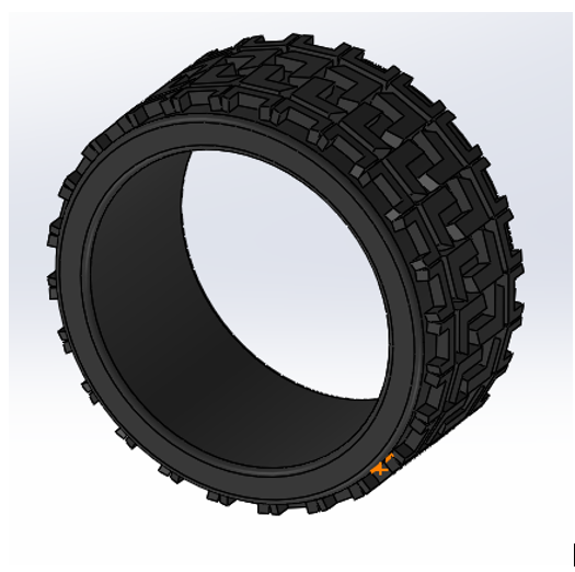
The Tyre:
A bit trickier, I struggled with the threads for ages until I came across a simple way to do it via the Web.
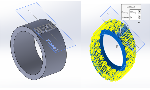
I made a ring that fitted onto the same radius as the frame and then added a plane above it to sketch on, then extruded it downwards. Another circular pattern, a few fillets and change the material to rubber and you’ve got
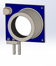
Ultrasonic Sensor:
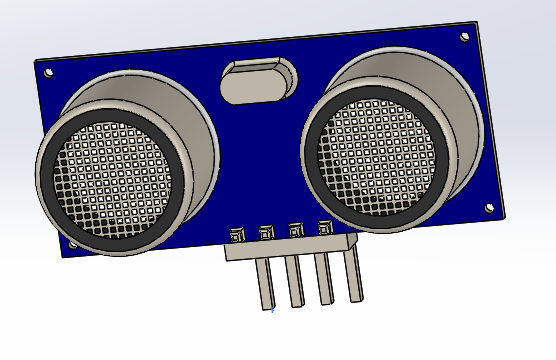
It’s amazing how good a bit of colouring makes a part look. This was relatively simple to make. I had the right half of the sensor and then just mirrored it around an axis to ensure symmetry and ease.
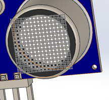
The toughest part was getting the grates above the circular extrudes which I solved by adding a linear sketch pattern of squares and extruding
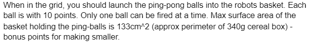
Elegoo Microcontroller:
15th March
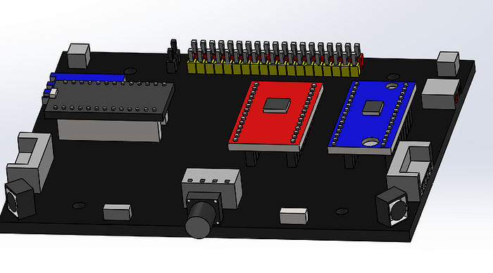
I won’t lie, I was hoping to find something via GrabCad or other that I could use instead however I couldn’t find anything so ended up making a simpler version myself. Didn’t go into too much detail as I didn’t feel the time spent on it would be warranted. Nothing too complex about this part.
12V DC Motor:
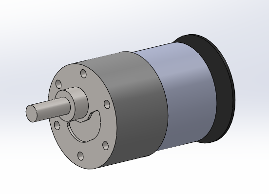
Once again, fairly standard. Simple sketches and extrusions.
Anyway, that’s the majority of the finalised parts and about as detailed as I plan to go.
Final Assembly
17th March
The brilliant thing about Assemblies in SolidWorks is that they continuously update if you edit the part and it’s already mated.
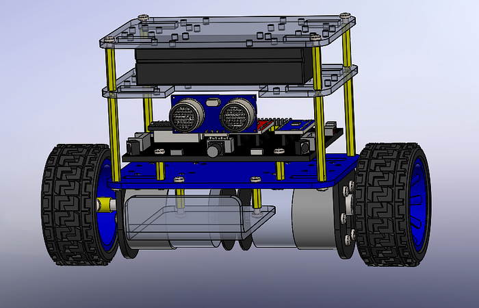
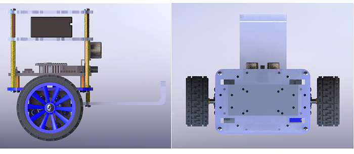
It looks great now that it’s coloured and properly mated. I set standard materials for a lot of the parts that give it an extra shine to it. Transparency was also edited for the acrylic plates and foothold to give it an opaque look. Here’s a few various views before rendering:
Final Rendering
18th March
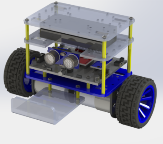
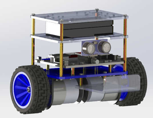
Here’s my first SolidWorks render. I used PhotoView 360. PhotoView 360 is a Solidworks add-in that produces photo-realistic renderings of Solidworks models. The rendered image incorporates the appearances, lighting, scene, and decals included with the model. It is amazing the difference rendering makes. The initial render made me spot a few discrepancies that I adjusted like luminosity and transparency of various pieces. here’s my final render below.

Final isometric render
Potential Improvements
19th March
I’m really happy with it, especially considering SolidWorks isn’t my strongest point. If I had more time I would’ve liked to go into more detail with the microcontroller and maybe added in wires. Other criticisms would maybe be the type of rubber that SolidWorks renders for the tyres and maybe I could’ve improved the threads on the tyres. All in all, it looks pretty similar to its Elegoo counterpart, especially considering I still haven’t seen the robot! I could’ve copped out and taken some pieces from GrabCad but I decided against it in the end and built it all from scratch by myself.
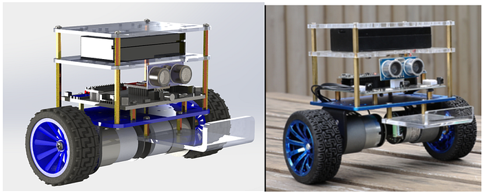
I think there’s always going to be aspects that you can continuously improve on but I feel my design has reached a point where it is photorealistic and abundantly clear what it is. This project was also a great way for me to showcase demonstrated CAD skills to possible employers and add it to my engineering portfolio.