Ping Pong Launcher
4th March
Well, I thought it was time to start simultaneously get cracking on the Ping-Pong launcher at the same time as the Rube Goldberg Machine. I was hoping to focus more on it when my Robot finally arrived but it’s not looking too promising. Anyway, on we go. The Ping-Pong Launcher (PPL) is part of the obstacle course which I’ll discuss in further blogs. For the moment here are the requirements;

I must build a device that harnesses potential energy and launches a PP over a 500ml water bottle into a cup the Elegoo Robot Supports.
Design Concepts
I drew rough drafts of the following design concepts which I’ll go through, then I’ll systematically decide which one to use using a weighting process where I decide what features are most essential to my design.

Concept 1: Basically I got a Lightbulb from my pulley system for the Rube Goldberg. Similar to a see-saw. I release the latch on the pulley and the heavier weight hits the side of the see-saw and forces the other side up launching the ball.
Advantages: I already have the pulley system rigged up and its housing.
Disadvantages: Have to clear a lot of height to get over the pulley system, reset time of the pulley also inconvenient.

Concept 2: Possibly my favourite concept. Releasing pneumatic air pressure forcing the Ping Pong to fly. Can pressurise the container easily via a bike tube valve, and distribute it evenly with the pressure valve
Advantages: Great use of engineering, a nice clean design and can store a lot of air, for multiple balls to fire
Disadvantages: A quick foraging of my house has informed me that I lack the materials to design this. I cant really find any pressurised container, or build one with stuff in my house.

Concept 3: A more trivial version of Concept 2, the balloon carries out the same function. A lot simpler to make.
Advantages: Easily obtained household components.
Disadvantages: A poor power source for multiple balls to be launched. A lot of lung power needed!
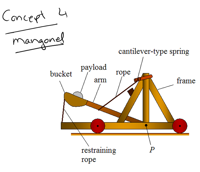
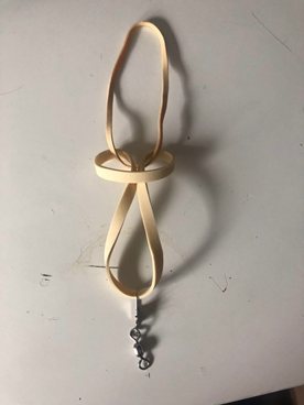
Concept 4: The Might Roman Mangonel, as Garrett Bennett once described it. A strong elastic band and latch restraining the catapult.
Advantages: Relatively simple materials, wood, plastic, elastic and a spoon type material. Would have a thorough understanding of the physics and equations involved from studying this design previously, and would be able to easily make improvements.
Disadvantages: If decide to use wood as a primary component of frame, it ‘wood’ be very time-consuming.
March 5th 2021

Weighing on the various metrics and rubrics required for this assignment, I chose this design based on 3 key factors:
- Manufacturability: Limited by materials in my home. This mangonel design is very manageable given its materials. They would consist of:
- Wood
- Elastic
- Steel
2. Predictability: Having constructed a Mangonel in Engineering Design I in my 1st Year of College. I have a great understanding of this design and various calculations involved like distance and angles of elevation required. It was quite accurate when we built it in 1st year and came 3rd in the in-house competition.
Basically, I know this design will work.
3. Design Constraints: This design will satisfy the key design specifications set out in the brief. It uses potential energy in the form of elastic under tension and is underneath the height requirement. The launcher's vertical height must be 90% or less than the bottle height.
Construction of Prototype
March 7th
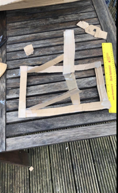
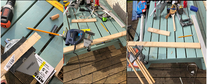
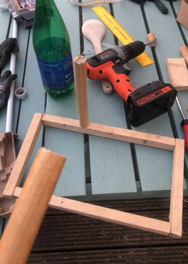
I began by creating a really quick prototype out of cardboard. This just helped me get an eye for rough dimensions. The next few pictures of me constructing the catapult out of spare wood I had in the shed. I added a thin metal rod. A wooden spoon and a small hook to tie the elastic band stolen from a slingshot to the frame.
Finished Prototype
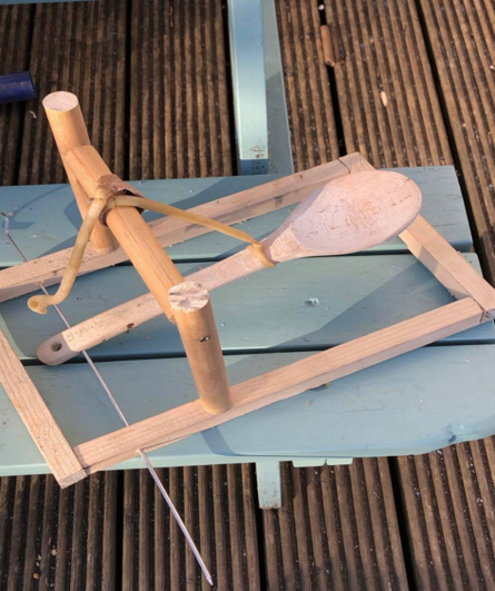
Test of Launcher 1
Above is a brief video of me testing the catapult. It looks very solid, I think I’ll get a great amount of consistency with it. This will require further testing in the week.
Update: Taking break from the ping pong launcher to focus on the CAD modelling for the next while. Make sure to check that blog out.
DISASTER!!!
March 9th
Well, it looks like we’re back to the drawing board. It turns out no energy sources can be added to the mangonel once the robot begins to navigate the course. In other words, I can’t keep drawing the mangonel backwards to fire it by hand. It needs to auto-reload. Unfortunately, I don’t possess anything to assist this auto-reloading function. I’ll have to bail hard on my design of the launcher. What an L!. I’m gonna get my thinking cap on for the next few days and try to figure it out.
Ping Pong Launcher II: A New Hope
April 2nd
Okay, so my lecturer has suggested a way of working around the multiple balls auto-reload the energy source feature. Implementing multiple launchers with multiple triggers. Unfortunately, I’ve kinda used up the majority of the good wood I had in my house so I’ll have to change the design slightly. I’ve been toying around a lot with the idea of elastic bands as a potential energy source. They’re a great way of storing and releasing large amounts of potential energy relative to the ping pong ball mass. So I started tinkering around with ideas on how to design a way to successfully fire ping pong balls using elastic. I was messing around with it and came up with this preliminary design.
Prototype 2.0
April 3rd
It’s not great, but it’s a start. The main idea is to have an effective way to fire the ball. This design is also pretty small so I could easily attach multiple launchers to the same wooden panel. It operates the same way as a slingshot, you draw the elastic back and release.
Materials Used:
Wood, Elastic, Cardboard, Nails
Prototype 2.1 — Multiple Launchers
April 5th
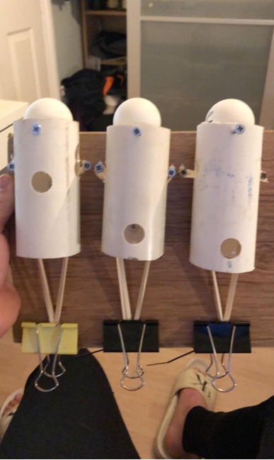
Okay so I doubled down on the prototype, I still haven't fully fixed dimensions. The small differences were:
- I used the plastic pipes from my broken goalposts as chambers to facilitate the launcher.
- Cable tied the elastic bands together
- 3 Launchers Built
- A screw at the top to stop the ball from falling through the tube
- BullDog clips to hold the elastic in tension
I’m really happy with how my design recovered after the catapult failure. I’ll hopefully build some sort of stand tomorrow and start testing accuracy a bit more.
Prototype 2.1 — Failure
April 9th
As the old saying goes, ‘Faile again, fail better’. I did a bit of testing and the problem was that the launcher balls just went flying too unpredictably. It was just the nature of the design. The elastic wasn’t uniform and was in too much tension so it just didn’t work very well. I’m not ditching this design completely however. I like the idea of the elastic and the pipes so I’ve made an alternate way to harness its potential energy. Here’s the accuracy problem below:
Not. Good.
Prototype 3.0 — Back in Business
This design involves simply wrapping the band around the elastic covering the tube. It seems to be:
- More Effective
- Simpler
- More standardised and uniform
I pursued this a bit further and followed off my 2.1 version to make:
I added a horrendous stand to just get a very quick feel for the launcher and how it operates. I added small fishing rig to latch on better to the bull dog clip. Accuracy levels were incredible in comparison to version 2.1. However, power levels slightly varied. This was largely down to the inconsistent lengths of the pipes. A longer pipe meant greater tension. A shorter pipe meant it went further. So once again I will improved the design. At least for the moment we have the following completed
- Good aim
- Multiple Balls
- Effective Triggers
Ready to build
April 11th
After multiple design iterations, I’m finally ready to start constructing the actual launcher. In fact, I made a CAD rendering to accurately scope out dimensions:
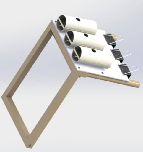
Obviously, this CAD model will look a lot cleaner than my actual piece. That’s the nature of using handheld tools and my glaring lack of DIY skills.
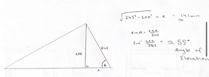
If you look closely, you might be able to guess that my frame is from my first design, the Mangonel. Like how they built Hill16 out of the 1916 Easter Rising rubble. The front frame measures 325mm on the hypotenuse. Then its width is 240mm. I’ll be using this to calculate angles later.
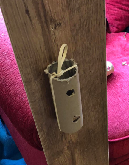
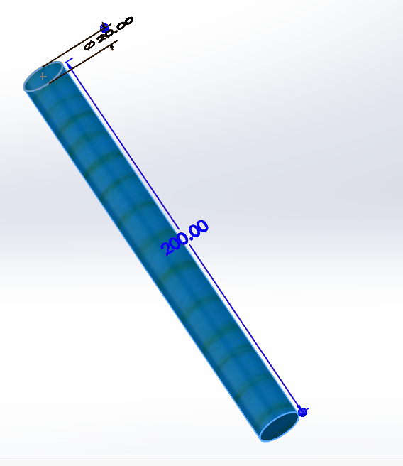
Design Components — The Pipe
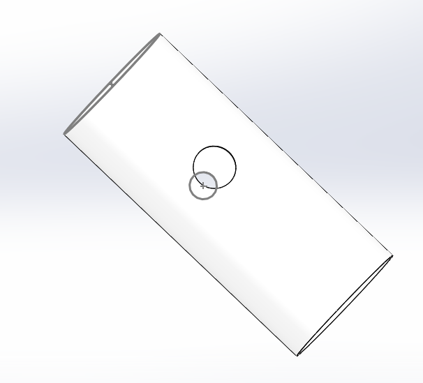
These are the size of the pipes, which I’ll be cutting as uniformly as possible. The larger holes are designed so I screw the Pipes into the Plate a lot easier. They’ll measure:
Length =120mm
Outer Diameter = 52mm
Inner Diameter = 50mm
Holes 5mm down from the top of the pipe*
See main plate for clearer dimensions
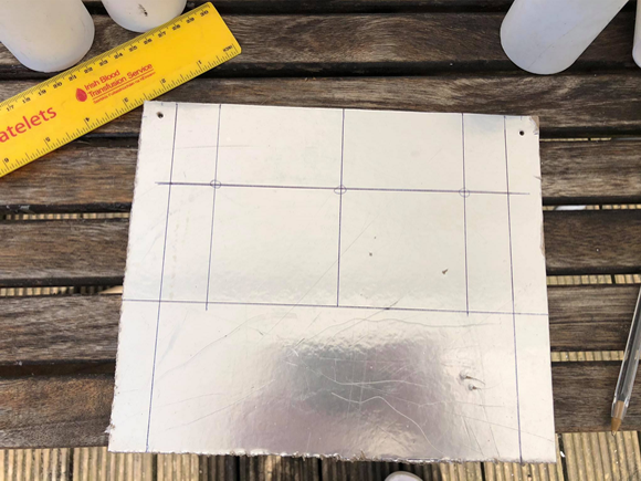
Design Components — The Plate
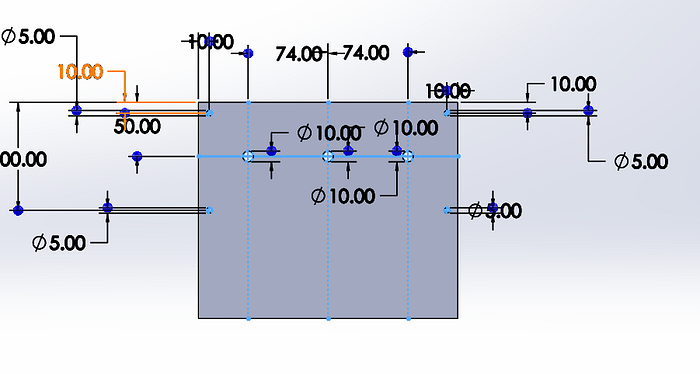
Here are the various dimensions for marking the holes for the plates. Holes may vary when it comes to actual construction because it depends on my drillbit sizes and screws, etc. The plate itself matches the width of the frame so it’s main dimensions are:
Height= 200mm
Width = 200mm
Thickness = 3mm
Design Components — Support Beams
That’s all the main components involved in its construction so I’ll get building it tomorrow.
Final Construction. (I Hope!)
April 12th
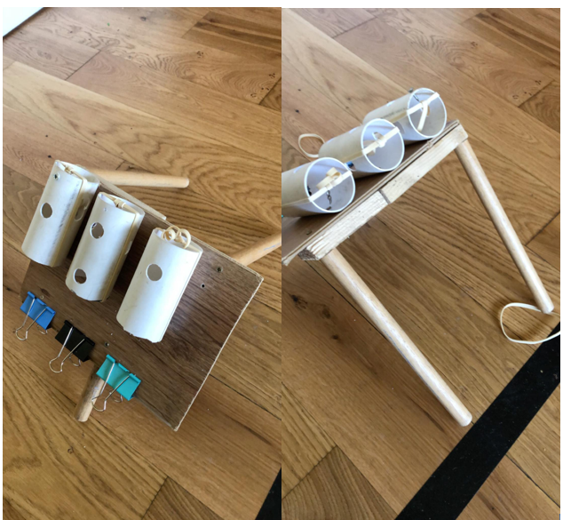
Marked the plate and securely gave space for the 3 launchers to attach the holes. Thank god for my A in Junior Cert Technology.
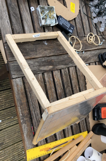
No problems here. I added a support or two under the plate.
Tough work but nearly there.
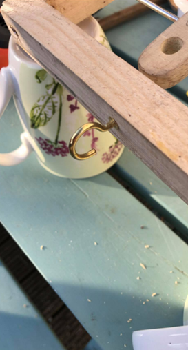
Just a quick note on how I looped the elastic around it. Also showing the fishing swivel which can be hooked under the bulldog clip.
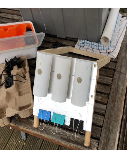
Finished Launcher
We did it.
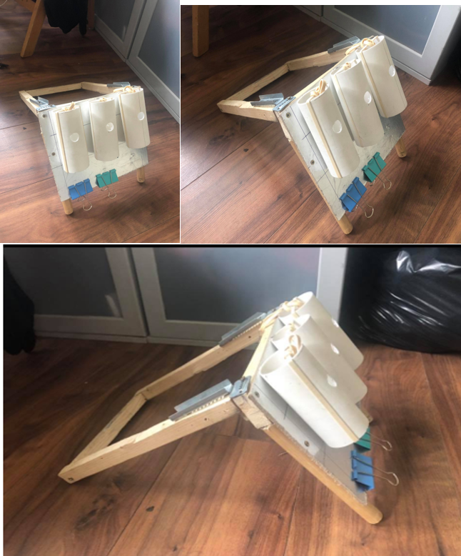
I added metal braces just to add an extra bit of support. Stil have to figure out angles for launching and various tensions but really happy with it. I said I’d leave it til tomorrow but here’s a quick trial run of me trying to hit the bucker
2/3 ain't bad on the first few tries. I’ll tweak the angles and the tensions more. At the minute, it’s almost launching too far but we’ll sort it later.
Energy Source and Calculations
April 13th
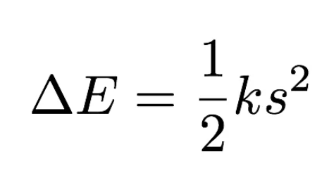
Elastic bands operate similarly to springs. They store potential energy and convert it to kinetic when released. Rubber bands provide an interesting contrast to springs. On stretching, they do not obey Hooke’s law very precisely. On unloading, they show hysteresis.
Hysteresis:
Hysteresis means that the magnitude of a resulting quantity is different during increases in the magnitude of the cause than during decreases, due to internal friction in a substance. Basically it means, that it doesn't return to its exact original shape after being used. I’ll have to watch out for this, and the fatigue life of the elastic bands. There’s a pretty good article by Wired.com that goes into a lot of depth about the energy storage of rubber bands that you can check out here. I’ll explain further down but I won’t go into too much detail regarding exact values for the bands. The bottom line is:
The more I stretch the band the further it will go. (Force = displacement x elastic constant. That’s all we need to worry about for this launcher.
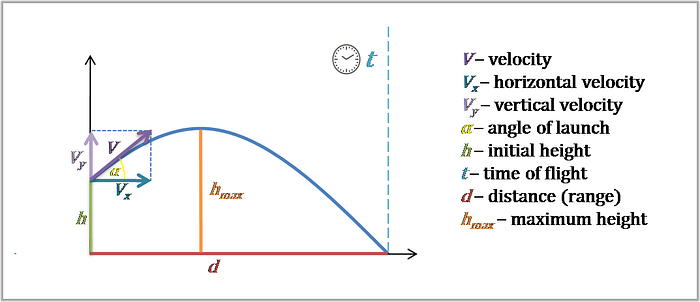
The Launcher is fully built and I’m really happy with it. It was a good way to get around the auto-reload feature by implementing multiple launchers. The exact distances and measurements will be written up in the Obstacle course blog but I’d thought I’d just so a basic amount here. In terms of calculations, I can’t really do a massive amount because I can’t calculate things like friction and air resistance. I can only control certain parameters like angles and tension.
For the purposes of this blog, I won’t be detailing what every small adjustment makes to the robot. But I’ll be measuring a few parameters
At the moment with current tension, my ball goes about 90cm. The goal is to get that down to around 55cm depending on the final specs of the course and the height of the robot basket.
I can do two things to reduce this distance:
- Reduce tension by
a) Getting a weaker elastic band
b)Displacing the band by a lesser distance. (Sort of like Hooke’s Law). The less I stretch the band, the less force it exerts.
2. Increase Angle of elevation to the point where it creates a big arc lowering its max range